|
Posted on June 29, 2023 @ 07:14:00 AM by Paul Meagher
We are hosting two weddings in our barn this year. So far we have hosted one wedding in the barn so we don't have alot of experience or client resources. The bride from our upcoming wedding asked whether we had a "floor plan" as they wanted to do some venue planning. As it happens, we don't have a floor plan but I said I could make one. I just sent her a floor plan I created this morning which she was ok with. I thought I would blog on some of the issue I ran into in coming up with a floor plan.
The first step in creating a floor plan was to take some measurements so I could create a spatially correct representation of the wedding event space. The wedding area does not consist of the whole barn so I didn't take measurements of the whole barn area, just the areas where the wedding would be taking place; what I refer to above as the "wedding event space". Also, there are three levels to the barn, so I only took measurements for the first level so far. It is a smaller wedding so the second and third levels will likely not be used.
The first measurements I made were the inside perimeter measurements. I deemed it necessary to indicate where all the doors were on the perimeter but not where all the windows were. These can be added in the future if needed. After getting the measurements for the main doors and perimeter I took some measurements for the distance and size of the stairs leading to the second level as this takes up quite a bit of space on the first level. I decided not to be too concerned about being completely accurate in my measurements and often rounded to the nearest foot or half foot.
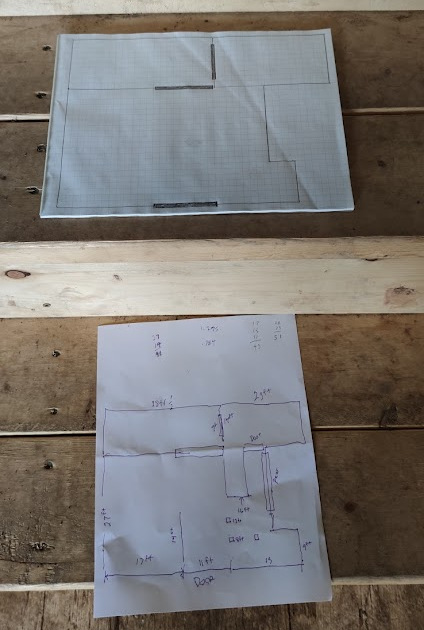
Once I had some measurements, I had to figure out how to diagram the floor plan. I looked into some software but decided that route might take too long so I resorted to using graph paper. Standing at the front sliding door of the barn, I knew the width measurement of the event space (53.5 feet) was greater than the depth measurement (41 feet) so I knew the graph paper would be oriented in landscape mode for the floor plan. There were 40 squares on the longest side of the graph paper so I divided 40 by the length of the longest side of the event space (53.5 feet)
and got the conversion factor I would apply (40/53.5) = 0.784 to all my foot measurements to get the number of grid squares it corresponded to. I then multiplied the longest depth measurement (41 feet) by the conversion factor (0.784) = 32.144 which I rounded to 32 squares. Luckily I had just enough squares running in the vertical orientation to accommodate the conversion factor so it worked out well; otherwise, I would have to estimate a smaller conversion factor that might work. Coming up with a good conversion factor between your measurement unit (feet or meters) and the corresponding size of a grid unit is critical. In my case 1 foot equaled .784 of a grid unit which is close to .75 or 3/4 of a grid unit.
Once you have your conversion factor you can draw the perimeter of your floor plan in a roughly accurate manner by converting each length measurement into the number of grid units (and partial grid units) it corresponds to. A roughly accurate floor plan was good enough for what I wanted the floor plan for but if I needed it to be more accurate I could record my length measurements more accurately (to the nearest 1/2 inch say) and graph the converted numbers more accurately (1 foot = .784 of a grid unit rather than .75 of a grid unit).
A floor plan can be developed iteratively. I took enough initial measurements to get the overall shape of the event space and the location of some main doors and the stairs. I plotted the points where these measurements began and ended and then used a ruler to draw lines through the points. I realized that I was missing measurements for a number of non-primary door locations and went back to the barn to get the measurements of where they were located and how wide they were. I also needed some more measurements to precisely locate the stairs on the floor plan.
Below are the two documents I started with. The top document is a basic outline of the event space based on the first set of measurements I took which are recorded in the second document. I eventually added more doors and the stairs to the top document and added more measurements to the bottom documents to properly graph them. Don't be surprised if you find the process of floor planning to be an iterative process of updating your floor plan and the document containing the measurements that it is based on.

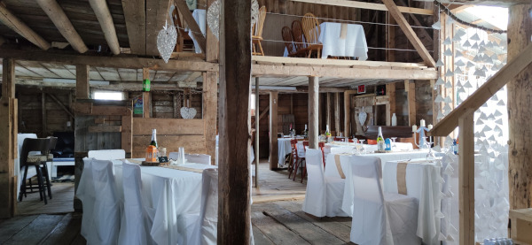
The next issue I ran into was how detailed you want your floor plan to be. Should all the doors be labelled with meaningful names or just letters? Should stairs and the head table area be labelled as such? Should the main entrance and exit points be labelled as such? This is when I decided I wanted to create a bare bones "base floor plan" that did not include any labeling and only include the most necessary aspects of the floor plan. I could always begin with this floor plan and add details to it in various ways for different purposes. What I did was I put my base floor plan in my printer and clicked the copy button. I then took the copy and marked it up with labels. It looked sloppy on the first copy so I made another copy and added labels again. That copy was a bit better but had some issues so I made another copy and added labels which was good enough that I took a photo and sent it to the client who was happy with the floor plan diagram. I also sent along a photo of what an actual wedding setup looked like in the barn so the floor plan was paired with some photographic imagery.
I realize there are good software solutions for the problem I was trying to solve and eventually I may digitalize my floor plan in software that will take my measurement info and create a perfect floor plan representation from it. If you find yourself in a situation similar to mine where you want to create a quick low tech solution then some of my suggestions above might be helpful in your efforts. The main suggestions are: measure the perimeter and main features first, decide the level of accuracy you require, if using graph paper figure out the conversion factor from your measurement unit (e.g., feet or meters) to a grid unit, graph your measurements, create a base floor plan without labels, make a copy of the base floor plan and apply labels and other details to that version of your floor plan to achieve a final result.
Low tech floor planning is a useful skill to have and can make you look more professional in your interactions with clients and regulators. If you are doing a renovation, you might want to follow this approach to creating a floor plan of your renovation. We eventually intend to use the event space for selling wine and will need to send a floor plan to regulators detailing how we are strictly separating retail and hospitality areas from manufacturing areas of the barn. Having a simplified base floor
plan without any labels is useful for creating floor plans that identify different features that are important to a particular clients interests in that space. Often these details can be added as "overlays" on top of the base floor plan. If you have a printer/scanner, you can achieve a similar result by printing out your base floor plan and marking it up with labels and other features for a final result.

Photo from first wedding we hosted in our barn
|
 AI Cyber Defense Dome Iron Dome for Cybersecurity Asset Protection
 Energy Miners, LLC is LIVE - Making Sales! $10K -$100K investment -> Passive and/or Active
 Unique proven 'battery' $500M+, $75M in commissions six-month pipeline. Final TWO Class A Units
 The Future of B2B Commerce: Buy Office Supplies. Build Business Credit. Boost Cash Flow! 277% ROI
 58-Year-Old Consumer Trusted Legacy Automotive Brand with Proven Results
 1-Way Deluxe: Blue Ocean RV/Boat Storage Opportunity: $10M Series A for 24% IRR in Houston Market
 Government, Commercial and Residential Construction est in 2019
  Master License Opportunity – Equine Salt Therapy USA Expansion
 Unattended Retail A.i. Software
  Bringing an honest auto repair shop to Corpus Christi
 High-Return Investment Opportunity in Oilfield Services
  FUELING COMMUNITY GROWTH THROUGH COFFEE
 Aviation Services Company business plan
 Equity or Debt or a Combination
 AI personal ad agency that saves 90% advertising budgets.
  Banjino’s Western Spritz: The Next Breakout Beverage Brand


